The content of this publication is subject to copyright of JSC TD ENERPRED and cannot be reproduced (even in part) without appropriate permission. JSC TD "ENERPRED" reserves the right to make any changes to the design and characteristics of the tool offered in this catalog without prior notice. Instrument specifications, including weight, dimensions and other parameters, may vary slightly.
| Model | Capacity, t | Pressure pushing / pulling, MPa | Stroke cylinder, mm | Diameter of the test equipment, mm | Length of the test equipment, mm | Force controlled compression and tension device, tf | Dimensions, mm (BxLxH) | Overall dimensions in transport position (BxLxH), mm | Weight, kg | |
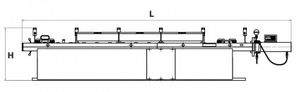
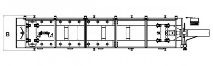
| SIG25G500 | 25,4/25,4 | 16,5/22 | 500 | 65 – 300 | 1000 – 3000 | 0,5 – 25 | 940×5172×1017 | 940×2577×1017/ 940×2745×1017 | 1200 | priceRequest |
| Model |
| SIG25G500 |
| Model | SIG25G500 | Capacity, t | 25,4/25,4 | Pressure pushing / pulling, MPa | 16,5/22 | Stroke cylinder, mm | 500 | Diameter of the test equipment, mm | 65 – 300 | Length of the test equipment, mm | 1000 – 3000 | Force controlled compression and tension device, tf | 0,5 – 25 | Dimensions, mm (BxLxH) | 940×5172×1017 | Overall dimensions in transport position (BxLxH), mm | 940×2577×1017/ 940×2745×1017 | Weight, kg | 1200 | priceRequest |
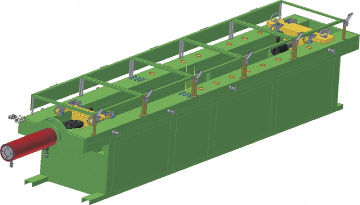
Testing on the installation is performed due to stretching or compression generated by the hydraulic cylinder rod movement and keeping under load for the specified time.
Ends of the tested equipment are inserted into cap fittings and fixed with pin-locks.
The cylinder rod is extended due to force generated when hydraulic liquid is supplied under pressure into the head end. The rod is returned to the initial position when hydraulic liquid is supplied into the cylinder rod end.
Major component parts of the installation are as follows:
Frame, hydraulic cylinder, carriage, pin-lock of the carriage, moveable carriage, load cell fixation, load cell, weighing indicator, digital pressure gauge, lifting screws, enclosure, high pressure hoses.
We have much to be proud of, because of our
partners leading companies in Russia and Eastern Europe:


If you have any questions, contact us and we will respond to them
Contact the managerWe invite you to mutually beneficial cooperation for the promotion of the tool marks "Enerpred" in all regions of our country and abroad.
Send requestWe offer you to download our product catalog in PDF format
Download